Willow Hardware User Manual
Contents
System Overview
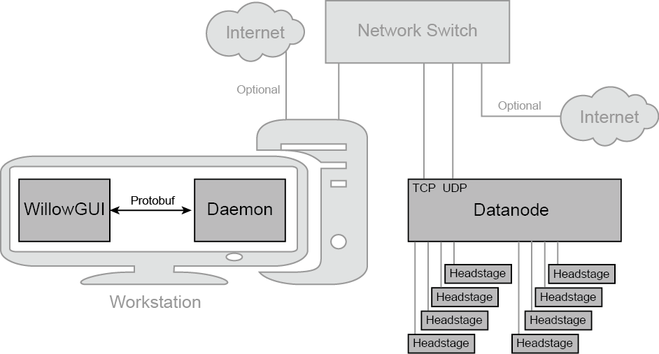
The Willow system is comprised of both hardware and software components. On the hardware side, there is the Datanode, which is the main data acquisition and storage computer. The Datanode collects data from the headstages, which are modular amplifier and digitizer boards. Each headstage acquires from 128 channels, and each Datanode can collect from as many as 8 headstages. The Datanode receives commands from the workstation - a computer running Linux. The Datanode and the workstation communicate over a high-speed Ethernet connection.
The workstation itself runs a multi-layered software stack. The Daemon handles the low-level communication with the Datanode, data collection, routing, and I/O. The daemon exposes a control interface based on Google’s Protocol Buffers (protobuf). The WillowGUI software wraps this control interface in some higher-level functions that allow the user to record, stream, an analyze data with the convenience of a graphical user interface.
Note
As of Willow 2.0, Linux is the only supported operating system.
Precautions
Our headstages incorporate four RHD2000 Series Digital Electrophysiology Interface Chips. According to the datasheet for these chips:
“All CMOS integrated circuits are susceptible to damage by exposure to electrostatic discharge (ESD) from charged bodies. Electrostatic charges of greater than 1000 V can accumulate on the human body or test equipment and can discharge without detection. All RHD2000 chips incorporate protection circuitry to guard against mild ESD events. However, permanent damage may occur on devices subjected to high energy electrostatic discharges. It is important for users to understand the nature of the ESD protection circuitry used on the chip.
On-chip passive elements (diodes and resistors) are used for ESD protection at the input to each amplifier. Diodes are connected to GND and VESD, and are used to bleed off charge quickly to prevent the voltage on the series capacitors from exceeding damaging levels. Small series resistors (370 Ω and 200 Ω) create voltage drops in response to large ESD currents, further protecting the amplifiers.”
Warning
Permanent damage may occur on devices subjected to high-energy electrostatic discharges. To avoid damaging the headstages, ensure the handler is grounded and thus free of electrostatic charge before handling any headstage. When not in use, headstages should be stored in an antistatic bag.
Performance Specs
Each Willow Datanode can acquire data from 1024 channels at 16-bit depth at 30 kHz. In addition, the Datanode has sufficient bandwidth to sample three auxiliary channels which can be chosen arbitrarily from any of the various registers in the RHD2132 chip, or from the current state of 16 GPIO channels on the DAQ module. By default the FPGA is programmed to automatically record the state of all GPIO pins at 2 kHz sample rate. In aggregate, this amounts to 1120 channels at 30 kS/s and 16-bit resolution.
The total data rate to acquire 1024 channels of data, including auxiliary data, meta-data and zero padding (each described in detail in the paper linked below), is 122.88 MB/s. At this data rate, a 512 GB hard drive, for example, can store up to 70 min of data from 1024 channels.
For more details, see A direct-to-drive neural data acquisition system.
How to Connect Hardware
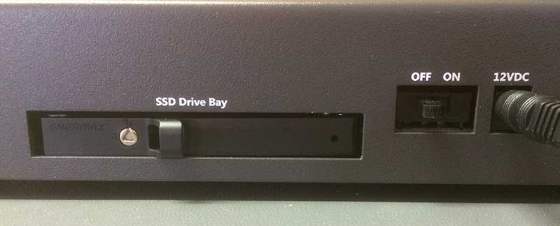
- Connect Datanode Power Supply to port labeled 12VDC on right side of Datanode.
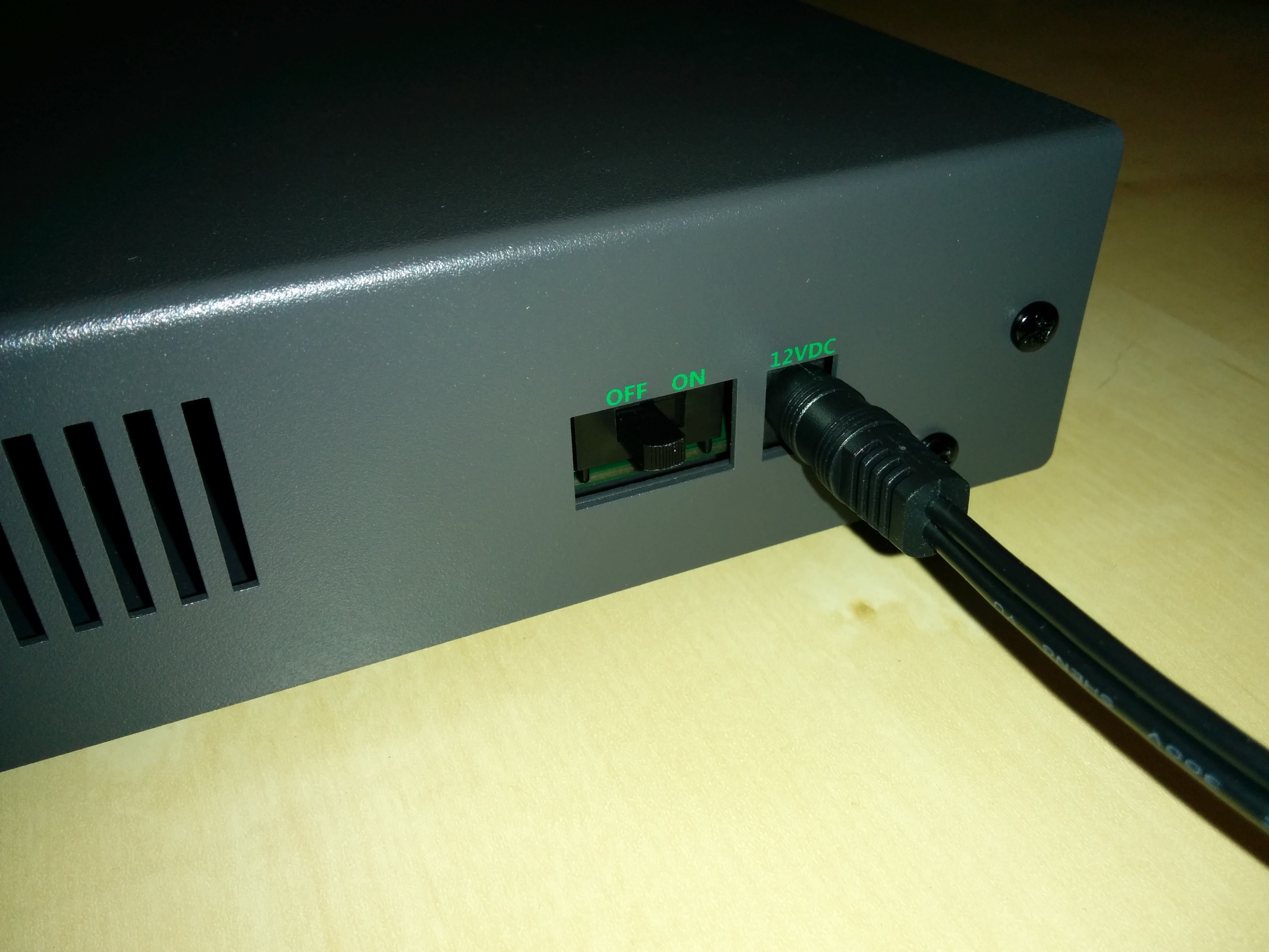
Figure 5. Datanode 12VDC power port and on/off switch.
Warning
All Willow Datanodes come with a floating 12VDC power supply, and are thus not grounded. This configuration allows the experimenter to chose how the Willow system is grounded for best signal quality, e.g. close to the animal. However, it also means that the experimenter must take care not to operate the Datanode in an ungrounded state such as with no headstages attached, lest static charge accumulate on the Datanode. Switching to a grounded power supply resolves any grounding concerns (since the Datanode is always grounded) at the risk of inferior signal quality due to increased noise.
- Connect TCP port and UDP port on Datanode to network switch (any two ports will do) using two Ethernet cables.
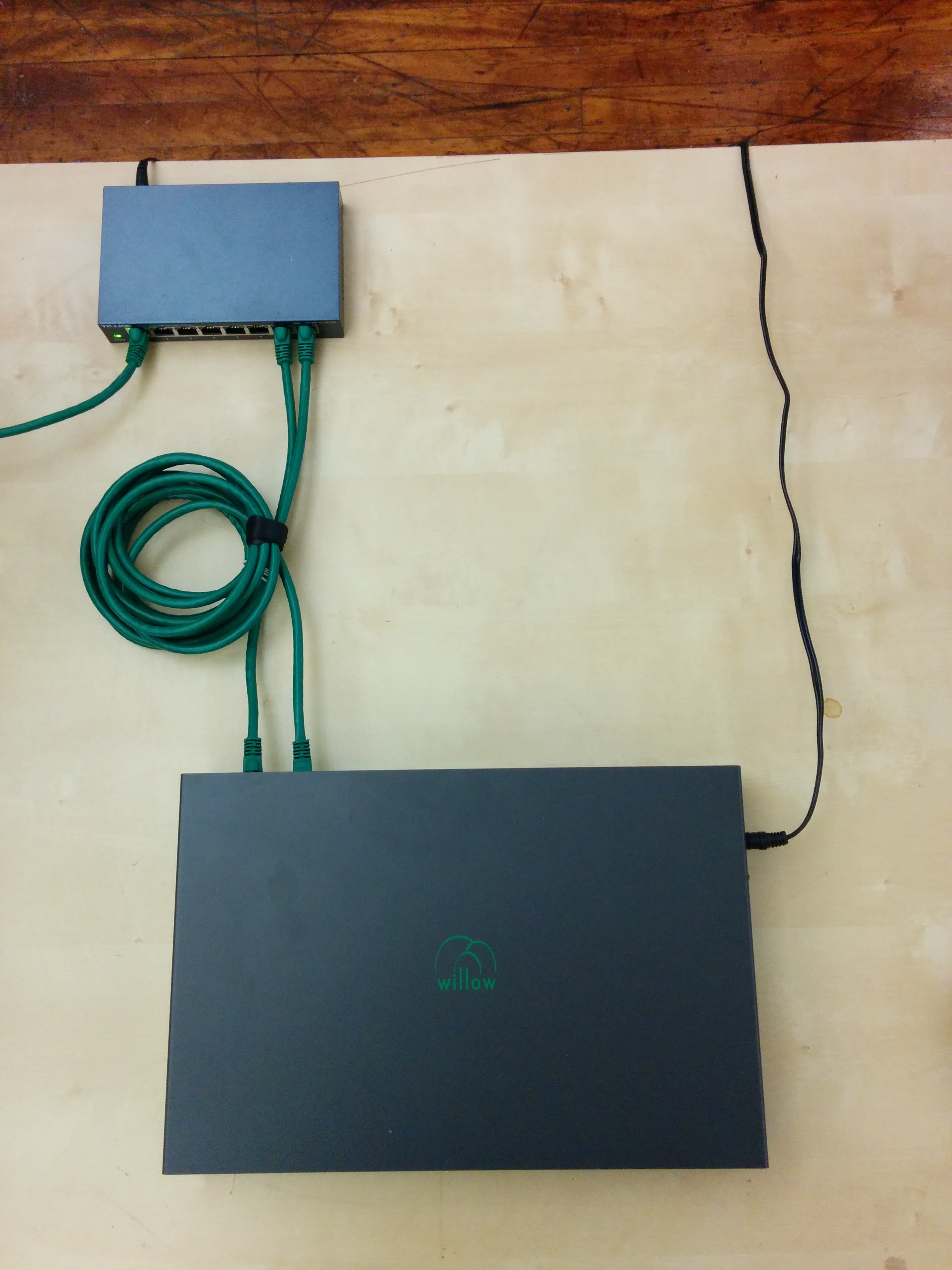
- Connect workstation to the same network switch via Ethernet cable. For information about networking with pre-configured workstations from LeafLabs, see Network Configuration.
- Connect Datanode to headstages via HDMI cables. Connect any Datanode MISO/MOSI paired-ports to respective MISO/MOSI paired-ports on any headstage. Repeat desired number of paired-port connections between Datanode and headstages, as needed. Arbitrary configurations of headstage connectivity at the MISO/MOSI interface is allowed, provided that at least one headstage is connected to the Datanode. If zero headstages are connected, then a snapshot will result in a timeout error.
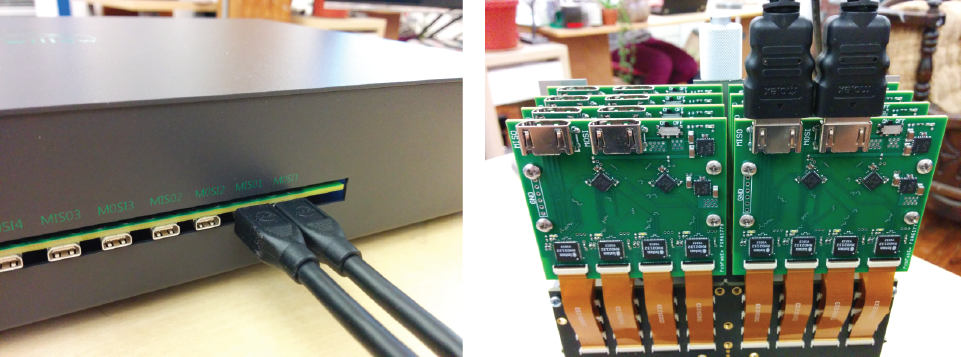
Figure 6. Example of Datanode paired-ports MISO1 and MOSI1 (left) connected to a headstage’s MISO/MOSI ports (right).
- Ensure that an SSD is in the drive bay.
- Slide power switch on side of Datanode to ON position to power Datanode. Wait until white LEDs on headstages flash twice (takes about 15 seconds) and then remain dark. At this point, the connection topology should look as shown in System Overview.
Note
The status of LEDs (lit vs not) is random before completion of initialization.
Network Configuration
A pre-configured workstation from LeafLabs has two NICs - one built-in to the motherboard (labelled Internet) and a second as a PCI card (labelled Willow) - to allow internet access while communicating with the WiIlow datanode. Each NIC is configured for one purpose or the other but not both. Thus, it is important to establish correct connectivity by following the labels.
In case the labels are missing or illegible, correct connectivity can still be determined. To begin, in the case of reversed connectivity, WillowGUI will display no connectivity to DataNode (even though the datanode can be pinged at 192.168.1.2) and no IP address will be issued by DHCP to NIC intended for internet (as seen by running ipconfig at a command prompt). To restore proper function, swap the ethernet cables connected to the workstation. WillowGUI will display no connectivity to Datanode (see Figure 7.) even though the datanode can be pinged at 192.168.1.2, and no IP address will be issued by DHCP to NIC intended for internet (as seen by running ipconfig at a command prompt). To restore proper function, swap the ethernet cables connected to the workstation.
To support high data rate network traffic, it is important configure the size in bytes of network packets. If you’re using a pre-configured Willow workstation, this happens automatically upon startup. In the case of a non-pre-configured workstation, a utility script is included with the Daemon in willow-daemon/util:
$ cd leafysd/util
$ ./expand_eth_buffers.sh <interface>
where <interface> is the name of your network interface (default is eth0).
Note
This script requires sudo privileges. See Login to the Workstation.
Troubleshooting
In WillowGUI, streaming works fine but snapshots fail and yield “empty” (KB instead of MB) files
Check the Network Configuration. Specifically, confirm that the MTU was increased from default (1500 bytes) to 4096.
What happens when capacity of SSD is less than configured in Settings?
For example, suppose the Datanode Storage Capacity in Settings is configured for 2 TB, but the SSD is 0.5 TB. What happens during a recording when the SSD fills up? The Datanode will present an error condition which will show up in the WillowGUI status bar. To clear the (hardware) error, the Datanode must be restarted by cycling its power.
If the WillowGUI or daemon software or even the workstation fails, what happens to the Willow Datanode?
Ideall, the Willow software suite is not supposed to fail, nor is the workstation, of course. Nevertheless, by design of the system, the WillowGUI and daemon can be killed without affecting the Willow Datanode operation. For example, recording will continue even as programs are killed. In fact, the workstation can be (if needed) re-booted without affecting the Datanode. After re-boot, simply start WillowGUI to launch daemon and re-connect to Willow DataNode.
Electrical noise is higher than expected.
Experiences electrophysiologists know that electrical noise can arise from any of a number of possible causes. The first thing to check is whether or not the Willow system is grounded. All Willow Datanodes come with a floating 12VDC power supply, and are thus not grounded. This configuration allows the experimenter to chose how the Willow system is grounded, e.g. close to the animal, for best signal quality.
However, make no assumption about whether the DC supply from any other power supply is connected to ground or not. Always measure the impedance from DC to AC on any power supply before using. It could be that the power supply has no connection to ground (so floating DC output), a sub-ohm (short-circuit) to ground, or some intermediate impedance to ground
Why should Willow users care about power supplies and connectivity to ground? If using a floating supply, then a ground connection must be added to headstages and/or sample to reduce noise. On the other hand, adding a ground connection when using a grounded power supply creates a ground loop which may increase noise. And power supplies with any impedance other than “zero or infinite” are unlikely to achieve low noise levels and should be avoided.o
No LEDs are lit on headstages
Check that the MISO/MOSI cables are correctly configured MISO to MISO and MOSI to MOSI. Accidentally connecting MOSI to MISO and vice versa will not damage the system, but neither will it work properly until properly connected.
Are headstages hot-swappable?
With the Willow Datanode powered-on, can headstages be dis/connected to the Datanode? No. Not only is there a risk of damage to sensitive circuitry caused electrical current transients, but also any newly-connected headstages will be uninitialized. Proper initialization of the neural chips on the headstages happens within 15 seconds of powering-on the Datanode only. Any headstages that are either powered-on or connected after Datanode boot will exist in an undefined state.
Network IP address conflicts
The Willow local area network domain is hard-coded in the FPGA on the Datanode to be 192.168.1.XXX. However, this same network domain is not uncommon for LANs. Thus, there is the potential for IP address conflict. Please contact us if your Willow Datanode needs a different IP address.
Are there indicator LEDs on Willow Datanode?
Yes, there are indicator LEDs on the Datanode PCB but the enclosure makes it all but impossible to see them. Since the Willow does not come with a warranty, feel free to remove the 8 screws holding the enclosure top to reveal the PCB and LEDs.
1. Green LED - located opposite corner of the board from the power connection - lit when 12 VDC power is supplied.
2. Blue LED - located on red microcontroller board - blinks when microcontroller is functioning correctly
3. Orange LEDs - located WHERE? - one LED indicates SOMETHING about user-controlled GPIO, and the other LED indicates an error in the FPGA logic
In addition, the TCP module (ADD PHOTO) has two (yellow and green) LEDs visible without removing the enclosure top.
The orange LED on the Datanode PCB is lit.
Whether due to accident, unexpected conditions, or undiscovered bugs in the system, an error condition may arise on the data node. This will be indicated by a solid orange LED staying lit near the USB connector (between the blue and green LEDs). There is a secondary orange LED which is user controlled GPIO and should not be confused with the error LED. Otherwise, an error flag has gone high somewhere in the FPGA logic, and needs to be cleared. The WillowGUI currently does not have a simple mechanism for clearing an error state in the hardware, so it is best to reset the FPGA by cycling the power.
The data node is not functional after powering on.
Just after power-on, the FPGA needs to self-program (“configure”) from a relatively slow flash memory chip; this process takes more than 10 seconds, during which the only indicator lights will be the microcontroller board and the green power LED (on the opposite corner of the board from the power switch).
If the green power LED does not come on when the power switch is in the On position, check that the power supply is the correct voltage (12v DC) and plugged in, and check for any shorts of the external power connectors.
If the green power LED does come on, but none of the other status LEDs on the board turn on (there should at least be a blinking blue LED near the set of buttons), even after waiting 30 seconds, it is possible that the FPGA configuration has been lost or than an earlier upload failed, and the configuration file needs to be re-uploaded over the USB port. This condition has never been observed.
WillowGUI cannot connect to data node.
Check network configuration on the host (must have static addressing configured and be on the same subnet as the datanode).
Check that the microcontroller has not frozen (reset it if the blue LED is not blinking on the red microcontroller board).
Check that the TCP module is powered up and connected to the network. Most ethernet switches will have a “link up” LED for each port; check that the port connected to the TCP module is active.
Note that the TCP module and microcontroller may take up to 10 seconds to respond to requests after a power on or microcontroller reset.
If both LEDs (yellow and green) on the TCP module are blinking at the same time, there has been a failure of communication between the module and microcontroller. Try resetting the microcontroller several times, or in the worst case power down the whole data node for 60 seconds before re-trying (and also notify LeafLabs of the problem!).
Channel data is all zeros.
This may be due to a headstage becoming disconnected or powered down. Valid data for a connected channel should never be all zero; the floating “zero voltage” should be around 32768 (half of 2^16) and have at least a couple bits (~5-10 counts) of noise even when the probe is grounded or tied to a stable voltage source. Check the “chip alive” metadata bits for the corresponding channels.
If reading back from disk, check that the experiment cookie is as expected (you may be reading back old empty data).
Headstage chips initialize correctly (blinking white LEDs), but the data node reports that headstage chips are not alive.
This condition can be caused by longer or shorter than normal cables between the datanode and headstages, resulting in valid commands sent to the headstages, but mangled data in the replies. Compensation is possible using FPGA compile-time flags; contact LeafLabs for details. The expected HDMI cable length is about 1.5 meters.